Basic Network Setup - Packet Tracer
Download and Setup Instructions:
Before starting this lab, make sure to have Cisco Packet Tracer downloaded, or is already downloaded on your current machine you are working on. If you do not have Cisco Packet Tracer downloaded, you will need to browse to the Cisco Packet Tracer website at https://www.netacad.com/courses/packet-tracer, here is where you can download the current version of Cisco Packet Tracer. You will need to make an account in order to download the application, you may also use this account in order to sign in. Upon downloading the application, go through the installation process and once done, start up the application into a blank Cisco Packet Tracer file, it should look something like this:
Housekeeping before jumping into the lab:
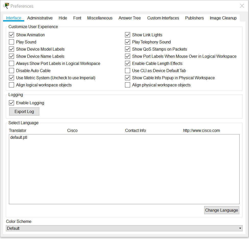
Cisco Packet Tracer can be used essentially right out of the gate with no further configuration necessarily needed. However, I will be asking you to turn on one setting that will make working within this virtual network creator a lot easier. Click on the Options button at the top and then click on Preferences. You can also access this menu by pressing CTRL+R. Now that you have the preferences window up, it should default be on the Interface tab, you should look for the option “Show Port Labels When Mouse Over in Logical Workspace”. This will allow you to easily see what devices have what information such as its IP when you hover over it in Packet Tracer. Once you have found it, make sure it has the check mark next to it. With that done, we can jump right into using Packet Tracer.
Communicating between Routers
Video to coincide with this part of the lab
Background Knowledge to cover before hand:
- What is Cisco Packet Tracer? Packet Tracer is a simulation tool created by Cisco in order to help create network topologies and mimic computer networking. From ethernet cables to CLIs this application really goes over everything that you will need to know to get started within the field of Networking. While oftentimes this is paired with the Cisco Network Associate Academy, this tool can be used for anyone to help design complex networks, which oftentimes would not be feasible due to price.
- What is a Router? A piece of hardware that helps connect other devices to the internet, or to each other. You can use them to create small local networks of devices, which is helpful if you would allow the sharing of files among devices or employees. Commonly confused with a modem. A modem connects you straight to the internet via an internet service provider, while a router connects many devices within a network, even the modem itself.
- What is an IP address? The unique address that helps identify a device on the internet or a local network. Can either be statically assigned via a user or automatically via DHCP.
- What is a gateway IP? The address on a network which sends traffic to other networks.
- What is a subnet mask? A 32 bit number that defines the range of IP addresses available within a network. Multiple subnet masks can organize a single network into smaller networks.
Let’s get started, one of the most important things to ensure when creating a network, is making sure that you can communicate between two devices. For this first example we are going to grab two routers and place them down in Packet Tracer.
Navigate to the bottom left of the screen, here you will be able to find various different icons that each represent various devices and connections within Packet Tracer. We are looking for the symbol on the bottom left hand, that looks like a disk. These are where the routers are located:
Upon clicking on it, you should see a bunch of various routers populating that bottom of the screen. These different routers represent various CISCO models in real life, while many of them have their unique differences by how they look and what modules you can add to them, working amongst all of them are very similar once you get a hang of it. For this section however, find the 1841 router. Once you do, go ahead and place two of them down. You can place them as far or as close a part as you want, as long as it looks something like this, you are in the clear:
Now what do we do with these two routers now that we placed them? We need to start to configure them, however, before we do that, we need to lay out some ground rules. Firstly, what will our IP and subnets for both of these routers be? If you are in a practice situation like this, it ultimately does not matter what you would want to choose, however constraints may be in place within real life that you would want to figure out such as how many users will be present on the network, creating room for possible expansion in the future and much more.
For this lab however we are going with the default subnet mask of
255.255.255.0, or a /24 address. The /24 subnet is a very common subnet
size as it is easy to understand, the first three octets being the same
number with the last octet, the host octet, being a zero. This subnet
mask allows for up to 256 addresses, plenty enough for our two router
configurations here. I should also mention, most times when working
within Packet Tracer, it will default to this subnet mask, going to show
you just how commonly it is used.
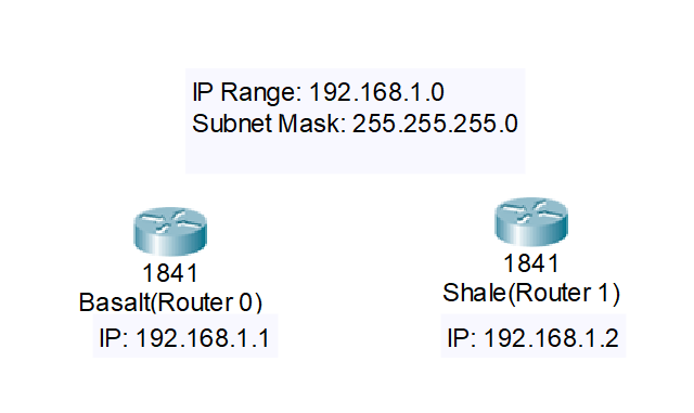
But what about IP? For our two routers, we will be on the 192.168.1.0 IP
range. With this being our range, and the subnet allowing 256 addresses,
that means we have between 192.168.1.0 and 192.168.1.255 right? Well,
not necessarily. You see the .0 address and the .255 address are not
usable as they are used for other purposes within networking. The
network identifier is often put at the .0 address, while the broadcast
address, or the address that is used to transmit data to all devices, is
at .255. Meaning we only have between 192.168.1.1 and 192.168.1.254 that
are usable for our network.
Great, now that we have this information, we should write it down somewhere to keep this in track. Thanks to Packet Tracer, you do not need to open an entire new word document or txt file, you can record a lot of this information directly in Packet Tracer itself. By pressing the N button, we can switch to note mode. While in Note mode, you can type in information by clicking anywhere on the screen and then begin typing away.
For this example, we will be recording our Subnet Mask, our IP range and
the two specific IPs we will use for our routers, which are 192.168.1.1
and 192.168.1.2. If you need to, you can grab the grayish area of the
notes blocks that are created and drag them to where you deem it to be
the most appropriate and helpful for you. You can also rename your
Routers to help keep track of information in Packet Tracer. To do this,
just double click on where you see “Router0” or “Router1”. Go ahead and
name the routers whatever you would like, for me I will be naming mine
“Basalt” and “Shale”. This is what my screen is looking like right now:
Now it is time to begin the configuration of the routers. First, double click Router0, here you will be greeted with a pop up window that shows you what the physical router looks like itself. Not only that but we can add different modules here as well that will allow you to have various different communication cables to be used. We will want to grab one of these and put one on right now, but first we need to turn off the router. On the right side of the router you should see an I/O switch, make sure to click it to turn it off. Once you have done that, we can add new modules to our router. The module we are looking for is the WIC-2T, which is listed off to the side. Go ahead and click on it and drag it to the hole on the right side of the router. What this does is allows a serial cable connection which while may not be commonplace in modern day networks, was used for long point to point connections and in some instances of packet tracer, is used to show off a WAN connection. You are mostly using it in here just for practice, as you could use any type of cable connection to have two routers communicate with each other.
Now that you have added the WIC-2T, turn the router back on. You will need to wait in order to begin configuring the router again, or you can use Packet Tracer’s speed up function. Once again, in the bottom left hand corner of your Packet Tracer window is the time, a stop watch and two arrows. The two arrows allow you to speed up time, by doing this you can skip over time it would take for a router to turn on or for a connection to register between two devices. Go ahead and click it, and then go into the config tab. Here is where you can begin to configure the router however you like.
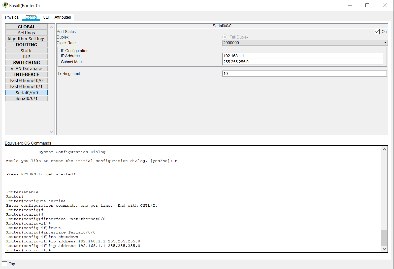
When you first get to this tab, you will be greeted with the Global Settings, where you can change the Display Name, Host Name and save your router settings. We do not need to deal with right now however, so go ahead and click on the Serial0/0/0 tab. By clicking on this, it will bring you to a menu where you can configure the IP address and subnet mask of this port. First you will need to turn the port on by check marking the On box. Once you have done that you can go ahead and type in your IP address and subnet mask. It should look like this when you are done!
With this done, go ahead and click on Settings under the Global tab, and then click on the Save button. This saves the configuration of your router and with that done, you are halfway done with configuring your set up!
You may think that we are just going to be repeating the same steps for the next router, but we are doing something different. While what we just went over is technically correct, you are not going to have this type of GUI for setting up a router all the time, so knowing the CLI commands will also be helpful to know. The only parts from last time you are going to repeat is adding the WIC-2T to the router, but once that is done head to the CLI tab.
You may be greeted with an automatic configuration message, if asked for
a yes or a no answer, respond with No. Once you are in the CLI, you
are going to type in the command enable in order to go into the
privileged mode of the CLI. Within the privileged mode you can run
commands that will save the configuration of the router and also show
routing information of the router, however this still is not where we
need to be. Type in configure terminal, this will bring us to the
part of the CLI where we can begin to assign IP addresses to specific
ports.
We are going to be configuring the Serial0/0/0 port on this router,
and to do so type in interface serial0/0/0 to bring you to the
config-if CLI. Here, is where we can now assign the IP address, as well
as turn on the port. To turn on the port, you will need to use the
shutdown command in a very specific way, by putting no in front
of it. no shutdown will turn on any interface for the router, and by
doing do will allow us to assign an IP to the interface. Now we assign
the interface the correct information, type in ip address 192.168.1.2 255.255.255.0. You will follow this method for every time you will
want to assign an IP via CLI. It will always follow the words ip
address, followed by the IP, followed by the subnet mask. Once you are
done with this, you can type in exit to leave the interface
configuration. Type in exit again to leave the general configuration
CLI, and once back in the enabled CLI, we will be using the command
copy running-config startup-config to save our settings. Just press
enter when it asks for a destination and you are set. For future
reference, you actually do not need to type out every single word for
most commands using the CLI here, for example you can just do copy run start in order to save the settings and conf t in order to access
the config CLI. Use this as much as you want for the future.
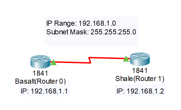
Now for the final part, connecting the two routers together. To do this, look for the light bolt symbol in the bottom left hand area where you found the routers. We are looking for a serial cable, which will be a red zig zag cable. You may see one with a clock here, do not choose that one, simply choose just the red one. Once you have clicked on the serial cable, go ahead and click on one of your routers. Upon doing so you shall see that it wants you to choose a port that this cable will be “plugged” into. Choose the serial 0/0/0 port, since we have just configured it, and then click on the other router and choose the same serial 0/0/0 port. Once done, your two routers should have a red zig zag going between them, with two green triangles showing that both ports are currently on!
Now time for the ultimate test, a ping between the two to make sure they
can communicate with each other! For our example, click on Router 0 and
then navigate to the CLI. Once you are in the default CLI (you can tell
this if you see Router followed by a > symbol), type in ping 192.168.1.2. It should then begin a sequence to tell if they can
communicate, if you are getting a success rate of 100, you are in the
clear! You may have a chance where one of the pings does not clear, that
is fine as this sometimes happens in real life scenarios as well,
communication can sometimes drop. With this done, we are finished with
our first section of Packet Tracer.
Communicating between Two End Devices using Static Routing
Video to coincide with this part of the lab
We are going to be starting this section off on a clean slate, so in order to create a new packet tracer instance, go ahead and go up to the file button in the left hand corner. Once you have clicked on that you are going to want to click on New. You can also accomplish this by pressing CTRL+N. It will ask you to save your packet tracer file, you can do this at your own discretion if you would like to save the work that we have done so far, I recommend doing so but ultimately it is up in your hands.
Now that we have a new Packet Tracer instance, the first thing we are going to do is grabbing the devices that we need in order to accomplish our task. Much like last time, we are going to need two routers, so go ahead and choose the 1841 routers once again. Also during this time, let’s add the WIC-2T modules to both routers, giving us the Serial connections again. After you have done that, we are going to need two end devices.
End devices can be simply considered to be either the source or the destination of data that is transmitted across the network. This can include many different devices within the Internet of Things such as Laptops, Desktops and Servers. For this instance, let us just choose two PCs. In order to get to End Devices, look in the left hand corner once more, the same area where we grab our routers from but you will want to click on the second button in the top row of buttons. This is what this should look like in order to easily visualize what I mean.
Now we can go ahead and drag two PCs into our topology. We have all the
devices that we need at this moment, however now we need to get into IP
and Subnet management. For communication between Router 0 and PC 0,
let’s go with the IP address of 192.168.2.0 and for Router 1 and PC 1,
let’s go with 192.168.3.0. Both of these networks will have the subnet
mask of 255.255.255.0. Now for communication between Router 0 and Router
1 let’s go with the IP address of 10.0.0.0, with the subnet mask of
255.255.255.252. This gives us four addresses, but only two usable
hosts, as 10.0.0.0 will be the IP range identifier while 10.0.0.3 is the
broadcast address. Our only two usable IP’s are 10.0.0.1 and 10.0.0.2,
which is perfect for this as we only need two IP addresses to
communicate between the two routers. Here is a picture of what I have
for my notes so far to help keep track of all of this information.
Let us start with the 192.168.2.0 IP network first. Click on Router0,
and by either using the CLI or the GUI, go to FastEthernet0/0. This will
be the port that will connect to PC0 on the 192.168.2.0 network, so for
this we should give it the first usable ip, being 192.168.2.1. Make sure
to turn on the port and then save after doing so, and then click on the
PC. Here you will see a physical representation of the PC, however, we
do not need to do anything here at the moment, so let’s head over to the
Desktop tab. Here we are given a lot of different options such as a Web
Browser, Firewall Settings and Email, the options we are looking for
though are the IP Configuration settings. Go ahead and click on that
option, doing so will give you a menu where you can type in the IP
Address of the computer, which will be 192.168.2.2. The Subnet mask
should default to 255.255.255.0, if not enter it manually, then we are
given the Default Gateway option. This address refers to the Router in
this case as it will lead our information out to remote network
segments, so this IP should be 192.168.2.1. With that done we are
finished with the first network.
Now let’s move onto the 192.168.3.0 network. We are going to be going
over the same steps as previously mentioned, this time being on Router 1
and PC 1 with the IP of 192.168.3.1 on the Router and 192.168.3.2 on the
PC. Take your time setting this up, and when you are done, we will need
to begin to configure the 10.0.0.0 network.
First, let’s go to Router0 and to the Serial 0/0/0 port, turn it on and
give it the 10.0.0.1 IP with the 255.255.255.252 subnet. Now, go over to
Router1 and set up 10.0.0.2 on the Serial 0/0/0 port on this device.
With this done, we have networked all of our devices, it is now time to
connect all of the devices to their respective pairs. Your topology
should look like this when you are done:
Now it is time for the test. Click on PC0, and when you are back on the
Desktop page, go to command prompt. Here is where we will issue a ping,
first let’s try to do a ping 192.168.2.1, this will show us that we
can connect to our Default gateway. This should be successful, if not go
back and check around with your configurations made so far and your
cable connections. Now try to ping 10.0.0.1, this should also
work, because even though they are on different subnets, the 10.0.0.1
address is still located on the same router as 192.168.2.1, meaning it
can connect to it. However, if you try to ping 192.168.3.2 this will
not work, as well as 192.168.3.1 and 10.0.0.2. It doesn’t simply fail
though, it should give you a Destination host unreachable, meaning it
doesn’t know how to connect to that host, which is where we can fix
this.
We are going to need to route the connections between each other
statically, there are other ways to do this, some you may be learning
about really soon, but for right now, statically routing the IP is what
we will be going over. Let’s start off by going to Router0, we need to
get to the configuration level of the CLI, to do that click on CLI, then
type in enable, followed by configure. Now that we are at the
configuration level, we will need to type in the routing information. It
follows this pattern, the IP Range Identifier, which is most of the time
.0 unless stated otherwise, the subnet mask, and then the port that the
router you currently on uses to get over onto that network, which in
Router0’s case, it would be the 10.0.0.2 port. Overall, the command
should look like this ip route 192.168.3.0 255.255.255.0 10.0.0.2.
This will statically route the 192.168.3.0 network onto this device, and
it accesses it by communicating with the 10.0.0.2 port. However, we need
to do this both ways in order to have a two way communication. Make sure
to save your Router0 configurations, and then head over to Router1’s
CLI. Here the command will look slightly different, as we are needing to
communicate with the opposite network this time, that being the
192.168.2.0 IP address, not only that but our Router1 will communicate
with the 10.0.0.1 port this time as well. The command should look like
ip route 192.168.2.0 255.255.255.0 10.0.0.1. With this done, and
with the configuration saved, go back over to PC0 and try to do ping 192.168.3.2 one more time. Even though you may fail initially, by
trying again, you should be able to get communication between these two
end devices. For test purposes, you can also go on PC1 and do a ping
192.168.2.2, but with that, we are finished with another section.
Router RIPv2 and OSPF:
Videos to coincide with this part of the lab:
Static:
RIP:
OSPF:
Static routing works, however it does take a substantial amount of time to get it up and running, not to mention you need to be very specific about how things are put within the routing configuration. In general, it just feels like a very manual process, but a very good back bone to have just in case a fiasco happens within your network. However, there are other ways we can go about routing to get communication across your network. That is by using Router Rip and OSPF. Before we get into any of this, we need to go over our topology we are going to be using for this section.
We are going to be upping the amount of routers we are going to be using, this time we are using three routers, each time with a single host attached to each one. In the network diagram below, there will be a general sense of what you will need to be assigned on each interface in order to get to a properly networked topology.
Once you have your network topology looking like one I have above, we can then get into how we will use our two new routing protocols. The first one we will be covering is RIP, also known as Routing Information Protocol. This is a dynamic routing protocol, which uses Hop Count, or the number of routers occurring in the source and destination network, to find the best path between the source and destination network. The path with the lowest amount of hops is always considered the best route and is placed within a routing table. RIP can’t be caught in a loop due to having a max hop count, which is 15, anything higher and it is considered unreachable. RIP is unique as it updates periodically by using the clock rates found on the Serial Interfaces, not only that but they are broadcasted meaning that it gets sent to all devices. There are three versions of RIP, RIP,RIPv2 and RIPing, we will be using RIPv2 for the lab, as it uses subnet masks for its routing updates.
To get started, save what we currently have completed, as a baseline, as
once we are done with Router RIP we will be loading it again to go over
the other protocol. Let’s make sure that each router has a proper clock
rate on its serial interfaces. First, go to Router 0 and go to Serial
0/0/0, within here is where we can set the clock rate, let’s set it at
64000. You can also set the clock rate by going to the CLI, accessing
the interface and typing in clock rate 64000. Only one side of a
connection needs the clock rate, so if we go to Serial 0/0/0 on Router 1
you can simply turn it off. To make sure the clock rate is being used,
and therefore RIP works, we need to use the other Red Serial Cable, the
one with the clock on it. To optimally use this, click on the router
that will be using its clock rate first, in our case Router 0 and then
connect it to the serial port that will not use its clock rate, that
being Router 1 serial 0/0/0. In order to check this, CTRL+R and
then click on Always Show Port Labels, to see which side is using the
clock rate.
We are not done with our clock rates however, as Router 1 is also
connected to Router 2, one of them will be needing to use clock rate,
while the other won’t, in this case, Router 1’s serial 0/0/1 will be
having a clock rate of 64000 while Router 2’s serial 0/0/0 wont.
With this out of the way, we can now begin the router rip process,
starting on Router0 we are going to need to go into the CLI and get to
configuration mode. Once inside we are going to need to type in router rip followed by version 2. This lets the router know that we are
using RIP and v2 as well. Once we have done that, we need to list the
network we are directly attached to, so for Router0 that would be the
192.168.1.0 and the 10.0.0.0 network. We do this by typing in network 192.168.1.0 and network 10.0.0.0 respectively. Once that is done
exit, we are done using RIP for this Router, so we move on to Router
1, and once inside of that router we will do RIP on 192.168.2.0,
10.0.0.0 and 11.0.0.0. Router 2 will have the networks of 11.0.0.0 and
192.168.3.0, and after that, we are done routing with the rip protocol.
You may need to advance time a bit to make sure the routing tables are
able to be sent, but once done, we can test out our connectivity by
going into PC0 and try to ping 192.168.2.2 and ping 192.168.3.2.
If any problem happens, make sure you are using the DCE Red Serial
wires, the one with the clock on it, and go to enable mode on the CLI
and run the command show ip route.
Once you have RIP working, reload the base save file you made after networking so we can test out OSPF, or Open Shortest Path First. This protocol is a link state protocol that also finds the shortest path between the routers to find the most efficient way to get there. Link-state means it is triggered by updates, meaning if a change is observed in the routing table, an update is triggered and sent throughout an area. OSPF is used for larger organizations, it has no hop count restriction, using bandwidth as a metric instead and uses areas to determine what routers to listen or talk to, this can therefore create one large area or multiple sub areas within a network.
Much like last time, set up your clock rates on your serial ports, I
want you to do this again for practice sake just to make sure you always
remember to set up DCE and clock rates while working with these routing
protocols. Once you have done that successfully, go to Router0 and once
inside, go to the configuration CLI level. Here is where we will create
an OSPF instance, you need a Process ID at the end of this command, as a
router can have multiple OSPF processes running, we want to make sure
that we are using the same one for each of our routers. You run router ospf 1 to create the OSPF instance, and once inside, we need to add
all the directly connected networks again.
This process is similar as the last time with RIP, with two major
differences, first being we need to add the area number, as that must be
the same among all routers that need to share info within a particular
instance. The other being is we need a wildcard subnet mask. This is
simply another way to write subnet masks, for our instance since we are
using 255.255.255.0 we are going to switch the 255’s and the 0’s,
meaning our wildcard mask will be 0.0.0.255. If we were to do it on
a subnet mask like 255.255.255.252, the wildcard would be 0.0.0.3.
Anyways, the commands you will want to run while on Router 0 are
network 192.168.1.0 0.255.255.255 area 0 and network 10.0.0.0 0.255.255.255 area 0. This will complete the information for OSPF on
Router 0, and with that, you can move onto Router 1 and 2. Once again,
make sure they all have the process id of 1 (router ospf 1), the
same area (area 0), and you are using the wildcard subnet. Router 1
will be the one with the most commands for you to type in, as it has the
most connected networks, keep that in mind when working on this.
Eventually, this should all be set up, once again, you can check the ip
route table by running show ip route in enabled mode, and make sure
to do a ping test across your network to make sure you have everything
complete and connected!
As a quick note, you could theoretically set up RIP and OSPF at the same time on these networks, however, there is not much sense to do so as they both will build databases and compute the shortest path. You could have OSPF and RIP in different parts of the network, but you would need a router to run both and then translate those routes from one protocol to another. Just figured I would let you know!
Setting up ASA:
Videos to coincide with this part of the lab:
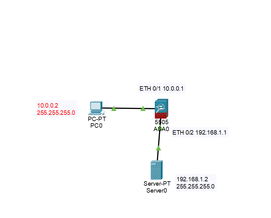
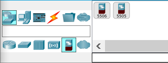
For our last topic, we are going to do a brief discussion about the cisco ASA firewall, and how to configure it between a LAN and a DMZ. In order to get access to the ASA firewall, you will want to make sure that you are under network devices, the area where you grab your routers, and then instead of grabbing a router, look for a button on the bottom that says security. Once you find it, grab a 5505 asa firewall.
Now that we have our firewall, we are going to need to do some configuration to it. Much like other firewalls, the Cisco ASA firewall brings a lot of protection, via a firewall, however unlike other pure firewalls, ASA contains antivirus, intrusion prevention, and much more. One of the things that ASA does when you bring it into a packet tracer, is that it comes with some default settings, particularly with VLANS. A VLAN is a local area network that maps devices rather than the location of the device, so say if you want a group of devices to behave as if they are a single network segment, you can do that via a VLAN even if they might not be.
The VLANS that the ASA server comes with are for outside connections and inside connections, which makes sense as a firewall would want to focus on things that are inside of it that it is protecting, as well as preventing nefarious things from the outside. One of the things that ASA has for its inside settings, are DHCP addresses, showing that you can use this firewall as a DHCP server as well. However we do not want that for our lab, so to fix this we are going to enter the CLI of ASA.
Once inside the ASA, you are going to run enable, it asks for a
password, but pressing enter should work for you. From there, go to the
configure level of the CLI and once inside run these commands to remove
DHCP from the inside VLAN. no dhcpd address 192.168.1.5-192.168.1.35 inside and no dhcpd enable inside. With this out of the way, you
go then do interface vlan 1 to configure the vlan ip, for this lets
set it as ip address 10.0.0.1 255.255.255.0.
The ASA server has an outside VLAN up, but for this lab, we are not going to deal with any outside connections for right now, so we can skip over VLAN 2. However, we need to set up VLAN 3, for our DMZ. A DMZ is used to protect an organization’s LAN from untrusted traffic, it functions as a bridge between public and private networks, so many businesses use a DMZ to put a web server on.
To create our VLAN 3, run interface vlan 3, once inside, run the
command no forward interface vlan1, we need to do this as with the
basic license of the 5505 ASA we have, we can not have more than two
interfaces that can be configured with a unique name that can access
each other. This will make it so the DMZ can’t connect to the inside
users, which is fine for us. After that, nameif dmz to name our
VLAN, security-level 50. The security level here is 50, because the
outside is set to 0 while the inside is set to 100. Meaning, that
traffic from inside our network is allowed to go to the DMZ from 100 to
50, and the DMZ can interact with the outside from 50 to 0. Finally,
let’s set an IP address of ip address 192.168.1.1 255.255.255.0.
With this done, the only other thing we need to do is assign an
interface on our ASA firewall to VLAN 3. Interface Ethernet 0/2 will
be used as it is one of the many inside interfaces we do not need, then
running the command switchport access vlan 3 will allow DMZ to rest
on this interface.
Our ASA firewall is almost complete now, the only thing we need to fix
is something that ASA should be doing for us normally, allowing higher
security levels to interact with lower security levels. We are going to
need to make a configuration to allow a TCP session between our host and
our HTTP server, by configuring a class-map, which classifies packets
based on the network traffic, a policy map, which uses class maps to
apply services to different groups of traffic, and then assign the
policy to our inside interface. To do this, make sure you are in
configure level and then run class-map HTTP to create our class map.
Once inside, match default-inspection-traffic, which will match the
default tcp and udp ports used by all applications that ASA can inspect.
Exit out and then run policy-map Web, the web can be named anything
you would want, but it makes sense to use our web server in this case.
Now inside, run class HTTP to specify our class map we just made and
then inspect http to focus on http traffic. Exit out and then by
running service-policy Web interface inside, this will allow our
inside connections to use the DMZ to browse the internet.
The only thing you need to do here is bring up a Server with the IP of
192.168.1.2, subnet of 255.255.255.0 and gateway of
192.168.1.1 and then a PC with 10.0.0.2, 255.255.255.0 and
10.0.0.1. Once done, go to the web browser and type in the server IP
of 192.168.1.2 and you should be able to browse to the website,
finishing your packet tracer labs for now!